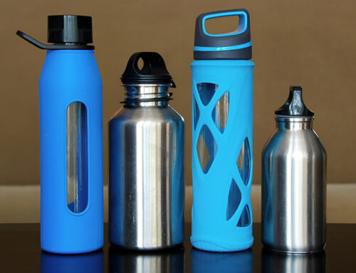
What is written in this article is how we design an injection mold for the custom plastic lid of a vacuum insulated stainless steel water bottle. The lid is injection molded, that is, high temperature melt plastic is injected into the mold, pressurized, cooled, solidified, and finally taken out from the mold to form a plastic cup lid. The main content of this article is: the requirements and key points of the design of the injection mold for the insulated water bottle lid / cap. This includes the properties of plastic products, the composition and structure of the mold and the injection molding machine, the points of attention for designing the composition of the mold, and the calculation of some important structures. Thereby, the design result of the entire mold is obtained. The design drawing software is autoCAD and Pro/e.
Product Process Analysis
Because of the characteristics of plastic products, the selection of product materials must be considered when producing and processing plastic cup lids. Different plastic materials have different material characteristics. Such as fluidity, shrinkage, etc. When designing the product, we must pay attention to the structure of the mold to facilitate the overall manufacture of the mold. When designing the product, pay attention to the simple structure, so that the mold manufacturing is simpler, and the wall thickness of the product should be uniform, because the plastic product has a certain shrinkage rate, different wall thickness will cause the product to deform, and the design of the cup cover should also ensure that it is easy to use . The point is to consider the economics of designing products and molds, that is, to produce products that meet the requirements at the lowest cost.

Main View

Top View
Quality requirements for bottle lids
Because this is a thermos bottle lid, his size requirements will be very strict, because if the size error is relatively large, it will affect the tightness of the entire vacuum flask, and the thermal insulation effect will be poor. Generally, the dimensional tolerance of the outer diameter circle of the cup cover should be kept within two. The dimensional deviation of the parting surface should be guaranteed within one line. This kind of accuracy requirements are relatively high, and electrical discharge machining is generally selected, so that the dimensional accuracy can be guaranteed to the greatest extent possible. The wall thickness of the cup lid should be as uniform as possible, so that it is easy to demold. The wall thickness of this product is 3mm.
Surface roughness of the lid
The surface roughness of the lid is the main factor that determines the quality of the lid. The surface roughness of the lid is mainly related to the roughness of the mold surface. Under normal circumstances, the surface roughness of the mold is 1-2 levels lower than the surface roughness of the product. In the case of continuous use of the mold, the surface roughness will continue to increase, then it is necessary to polish in time. Different cup lid products have different requirements on the surface roughness of the male mold core and the female mold core. The transparent cup cover requires the same surface roughness of the two mold cores. The opaque cup cover needs to be determined according to the situation.
The tilt of the cup lid
When the product is cooled and solidified in the mold, it will shrink due to the relationship of thermal expansion and contraction. Therefore, before the ejection mechanism ejects the product, the product will tightly wrap the male mold before the film is removed. In order to prevent problems such as scratches when the product is stripped, the mold stripping slope will be considered when designing the mold core. However, the cup cover does not have a high requirement for the mold release slope, so it will not be described in detail here.
Material of the lid
The main material of the cup lid is polypropylene (PP). Polypropylene is a semi-crystalline material. It is an excellent resin variety. When uncolored, it is white and translucent, wax-like, odorless and non-toxic. Polypropylene has a high shrinkage rate, probably between 1% and 2.5%, which leads to problems such as deformation and shrinkage in the production process of polyethylene lids. Bottle lid products are normally produced in large quantities.
Selection of Injection Molding Machine
The injection molds for cup lids produced by KingStar are usually one mold with two cavities and one mold with four cavities. Rarely will there be one mold with one cavity. One mold and one cavity are usually used to produce relatively large plastic products, while one mold and four cavities are used to produce relatively small products. This article discusses the commonly used two-cavity mold.
The performance of the horizontal injection molding machine used in this product is as follows:
Rated injection volume: 125cm³
Screw (plunger) diameter: 42mm
Injection pressure: 120MPa
Injection stroke: 115mm
Injection method: screw type
Clamping force: 900kN
Maximum molding area: 320cm2
Maximum mold opening stroke: 300mm
Maximum thickness of mold: 300mm
The minimum thickness of the mold: 200mm
Nozzle arc radius: 12mm
Nozzle hole radius: 4mm
Ejection method: there is no ejector rod on both sides, and the ejector is mechanical
Tie rod space: 260 * 290mm
Fixed plate size of dynamic fixed mold: 428 * 458mm
Clamping mode: hydraulic-mechanical
Injection volume check
It can be known from the product that its mass is 30 grams. Because this cup lid is processed by one mold and two cavities, the volume of the pouring system of the mold is 15.72 cm³
By the formula:
Product V = m / p = 30 / 0.905 = 33.15cm³
V total = v pouring + v product
= 15.72cm³ + 33.15 * 2cm³
= 82.02cm³
Injection volume check formula, 0.8V machine> = V total
V machine = 125 cm³> V total / 0.8 = 102.53 cm³
This formula is established, you can choose this injection molding machine.
Injection pressure check
From the performance of the injection molding machine above, the injection pressure of the injection molding machine is 120MPa, and the injection pressure of the cup cover is about 80MPa. Here we take 80MPa. Because the injection pressure of the injection molding machine is 120> 80, it meets the requirements.
Checking of injection molding clamping force
The formula for checking the clamping force is p (nA + A1) ≤F
In the formula: F—the rated clamping force of the injection molding machine
A— The projected area of a single plastic part on the mold parting surface
A1—Projected area of casting system on mold parting surface
P—the molding pressure of the plastic melt on the cavity
According to the size of the plastic parts: A = 2826 mm2, A1 = 1300 mm2
P (nA + A1) = 80 * (2 * 2826 + 1300) = 556160N is less than the rated clamping force of the injection molding machine 900KN, so it meets the requirements.
Checking the mold opening stroke
Mold opening stroke check formula s≥H + H1 + (5-10) mm
In the formula: H-launch distance (can also be used as the height of the punch) (mm);
H1—The height of the plastic parts including the pouring system (mm);
S-the maximum stroke of the moving plate of the injection machine (mm);
H + H1 + (5-10) = 20 + 75 + 10 = 105mm
According to the performance of the injection molding machine above, the maximum mold opening stroke of the injection molding machine is 300mm> 105mm, so the injection molding machine meets the requirements.
Summary
In summary, the horizontal injection molding machine can be used to produce the cup lid product.
Parting Surface Design
The parting surface refers to the separable product removed from the mold, and the contact surface is called the parting surface. The parting surface may be perpendicular to the mold clamping direction, or may be parallel or inclined to the mold clamping direction. The parting surface of this product is taken on the maximum outer diameter of the product, so the parting surface is taken on the bottom surface. Since the mold used to produce this product is a two-cavity mold and uses point inbreeding, the mold uses a double-parting mold.
Considerations for designing parting surfaces
- To ensure the dimensional accuracy of the product
- To ensure the surface requirements of the product
The principle of selecting the parting surface for this product
- In order to facilitate mold opening, the design of the parting surface generally requires that the product be left on the male mold, which can prevent the product from sticking to the female mold, but pay attention to whether this design will affect the appearance of the product.
- To facilitate exhaust
- To help prevent overflow
- To facilitate the consideration of processing intensity

Figure 3-1 Parting Surface
Design of Pouring System
The pouring system in the mold refers to the flow path of plastic liquid from the nozzle of the injection molding machine to the cavity of the mold. This runner is composed of main channel, runner, gate and cold feed well. The main channel refers to the beginning of the nozzle to the end of the runner, and the runner refers to the end of the main channel and the end of the gate. The sprue bushing is also a part of the main runner. Because the main runner has to contact and collide with the nozzle of the high-temperature plastic machine, the beginning part of the main runner of the mold is usually designed as a detachable and replaced sprue bushing. Gate refers to the distance from the end of the runner to the end of the product. Cold feed wells, also known as cold feed pockets, are used to store cold feed heads generated during the injection interval.

1-main channel 2-cold material cavity 3-diversion channel 4-cavity
Figure 4-1 Pouring System
Design of Mainstream Road
The main channel is conical, with a taper of 2 ° and a single side of 1 °. The main channel should not be too long. If it is too long, the plastic melt will cool down in the flow channel, which will affect the quality of the product. Here, the flow channel is 50mm. The reason why the main road is designed to be tapered is to remove the plastic in the main road smoothly.

Figure 4-2 Mainstream
Design of Shunt
The mold in this article is a two-cavity mold, so it is necessary to set up a shunt, design the shunt as short as possible, and reduce the number of bends, which can reduce the loss of pressure and heat into a font.

Figure 4-3: Cross-sectional View of Shunt
Sprue Bushing
Because the main channel is often in contact with the nozzle of the injection machine, it is easy to be damaged. In order to facilitate maintenance, the main channel is set in the sprue sleeve. The sprue sleeve is usually processed with good materials alone, which is not only convenient for disassembly and assembly but also damaged It is also easy to repair or replace.

Figure 4-4: Intersection Sets
Gate Design
The gate is divided into fan-shaped pouring, side pouring, point pouring, latent pouring, horn pouring, overlapping pouring, tab pouring, etc. according to the different shapes and positions. The die in this article uses point-in-place pouring, which has the advantage of facilitating the formation of shear rate-sensitive plastics. Although the gate is not large, it is indeed a more important part. Its position, shape, and size will affect the quality and performance of the product. Therefore, pay attention to when choosing the gate:
- Try to shorten the flow distance
- The gate is located in the thick wall of the product
- Avoid product defects due to melt rupture
- Consider the influence of molecular orientation
- Reduce welding marks
In order to achieve automatic film release, the cup lid products in this article adopt point-in-water pouring.
Cold Cavity Design
The length of the cold cavity is generally designed to be 1.5-2 times the diameter of the main channel. The cold cavity not only prevents cold material from entering the cavity and affects the quality of the product, but also allows the molten material to fill the cavity smoothly. In the location of the cold cavity, a pull pin can be arranged to divide the mold. The condensate in the main channel can be taken out through the pulling needle.
Design of Temperature Regulation System

In this article, the material of the cup lid product is pp. According to the table, the molding temperature is 200-270, and the mold temperature is 20-60. Generally, the mold temperature for producing this product is maintained at 50 ° C. The mold temperature refers to the surface temperature of the male mold core and the female mold core of the mold. Whether the temperature of the mold is stable or not and whether the temperature is appropriate will directly affect the quality of the lid product. Before the lid product is produced, the mold must be preheated, and when the appropriate temperature is reached, the processing will start. This is done to avoid filling difficulties.
The cooling system is also called the temperature control system. The cooling system is not only related to the quality of the mold plastic products, but also related to the production efficiency of the mold.
- The role of mold waterway:
Control the temperature of the mold so that the products in the mold are rapidly formed, and sometimes the temperature of the mold cavity needs to be maintained to control the molding time of the product and ensure the quality of the product.
- Control method of mold temperature
Set a waterway inside the mold.
- Checkpoints of the cooling system
During production and processing, the temperature of the water in the waterway just when it enters the mold is compared with the temperature when the water comes out of the mold. The temperature of the water in and the temperature of the water should not exceed 5 degrees.
- Waterway configuration
Gate cooling (enhanced cooling near the gate)
In theory, the waterway is best to be equidistant from the product. In practice, the operation is simply impossible. The specific analysis of the specific problems of the arrangement of the waterway is not how you want to arrange it. They are complementary to each other and constrain each other, but there is a basic principle for the layout of the waterway. If the cooling is uniform, if the cooling is uneven, it will cause defects such as poor molding of the produced product, unstable dimensions, and deformation.
Calculation of Cooling Water Channel Size
- Calculation of cooling water surface area
Injection molding is calculated once per minute, the water flow rate is 2.14m / s, and the pore diameter is calculated according to 0.8mm.
Calculation formula of cooling water surface area: A = Mq / 3600a (θm-θw) = 3.6 * 5.9 / 3600 * a (26.5-25) = 4729 mm²
Where A—the total surface area of the cooling water channel,
M—the mass of resin injected into the mold per unit time
q—The heat released per unit mass of resin in the mold
a—surface heat transfer coefficient of cooling water
θm— Molding surface temperature
θw—the average temperature of cooling water
- Calculation of the total length of cooling water
Calculation of total length of cooling water channel: L = 1000A / 3.14d = 1.88m
L—total length of cooling circuit
A—total surface area of cooling water
D—Diameter of cooling water hole
Clamping Guide Mechanism Design
The clamping guide mechanism is a mechanism to ensure that the male and female molds can be correctly positioned and guided when the mold is closed. The main functions of the mold clamping guide mechanism are: positioning, guiding and withstanding a certain lateral pressure. The most commonly used guide mechanism is the guide column guide mechanism. The guide column guide mechanism is generally composed of a guide column, a guide sleeve and a guide hole.
Design of the Guide Post
There are usually 8 guide posts in a set of injection molds. When closing the mold, the oil grooves of the guide posts should be greased to play a lubricating role. The guide part of the guide post is generally 8-12 mm higher than the punch, which can prevent the male mold from entering the female mold first and causing some accidents when closing the mold. The shape of the head of the guide column is generally hemispherical, so that the guide column can easily enter the guide hole. The size of the head of the guide column is not very strict. Generally, it is only necessary to grind a rough shape on the grinder. The guide post generally requires that its material properties are wear-resistant and not easy to break, so 20 steel is mostly used. The guide posts are generally distributed at the four corners of the male and female molds of the mold, and there are four guide posts for the male and female molds. The diameter of the guide post is related to its position on the template. The diameter of the guide post is generally 1 to 1.5 times the distance between the guide post and the template. For example, the diameter of the mold guide post is 25 mm, and it is 30 mm long and 40 mm wide from the edge of the mold.

Figure 6-1: Guide Post
Design of Guide Bush
The front end of the guide sleeve must be chamfered, so that the guide post can easily enter the guide sleeve. The material of the guide sleeve is generally a harder material, but the hardness must be lower than that of the guide post, which can reduce the wear on the guide post. The guide sleeve is still relatively tight in the template, but in order to put it in the mold opening, the guide sleeve is usually brought out by the guide post. Generally, a small hole is punched in the template and the guide sleeve is fastened with screws.

Figure 6-1: Guide Sleeve
Design of Guide Hole
The guide hole is divided into a guide hole with a guide sleeve and a guide hole without a guide. The general processing accuracy is not very high, as long as the guide post can pass smoothly, but it cannot be processed too large, so it will not play the role of guidance. The guide sleeve may also be unusable.
Exhaust System Design
The exhaust system refers to the exhaust of the gas in the cavity during plastic molding. Exhaust in the injection mold is a more important issue in the mold design. In order to exhaust the air in the cavity during production and processing, it is often necessary to open an exhaust groove on the parting surface or disassemble the sub. The depth of the exhaust slot is generally two, the depth is not easy to master, generally use electrical discharge machining, a few times with a low current, the exhaust slot can not be opened too large, otherwise the product will be burr.
When the exhaust is poor, the products produced will have a series of quality problems. The main performance is as follows: the plastic melt cannot fill the cavity, and the produced product has bubbles, trapped gas and obvious welding lines. Problems caused by poor exhaust:
- During the production of plastic products, the plastic melt will enter the cavity and squeeze the gas out of the cavity. If the gas in the cavity is not exhausted in time, it will cause difficulty in filling the plastic melt and cause injection Insufficient amount to fill the entire cavity of the mold.
- Failure to exhaust the gas in the mold cavity in time will form a high pressure in the mold cavity, and will penetrate into the product under a certain degree of compression, resulting in product quality defects.
- Because the gas is highly compressed during the injection molding process, the temperature in the cavity rises sharply, which causes the surrounding melt to decompose and burn, causing local carbonization and scorching of the plastic parts.
- The gas in the mold cavity is not well removed, so that the plastic melt entering each cavity has a different speed, so it is easy to form flow marks and fusion marks, and reduce the mechanical properties of the plastic parts.
- Due to the obstruction of the gas in the cavity, the filling speed will be reduced, the molding cycle will be affected, and the production efficiency will be reduced.
Mold Structure and Size Calculation
The Structure of the Cavity
The cavity is inlaid, which is easy to process. It is inlaid on the mother template. This inlaid mold kernel is fixed on the mother template with screws. Because the inlaid mold kernels are generally small in size, most of these inlaid mold kernels are easy to maintain. It can also avoid the scrapping of the entire template due to the damage of the mold core.

Figure 8-1: Cavity
Calculation of the radial dimension of the cavity
Formula for calculating the radial dimension of the cavity:
Dm=(D+DQ-3/4△)
Dm—The radial dimension of the cavity
b—manufacturing error of moulded parts
D—The maximum size of the product
Q—shrinkage rate of product material
△—Product tolerance
3 / 4—coefficient, take 3/4 here
Core Structure
The core is also inlaid, inlaid on the common form. This inlaid male mold kernel is easy to process, and the male mold kernel is inlaid on the male template to form the internal structure of the cup cover. Because the lid is made of plastic and has a certain shrinkage rate, you should pay attention to this when designing the male mold.

Figure 8-1: Core
Cavity Depth and Core Height Dimension Calculation
Cavity depth dimension calculation
Calculation formula of cavity depth dimension: Hm=(h+hQ-2/3△)
Hm—cavity depth
h—Maximum size of product height
Hm=(20+20*0.016-2/3*0.36)=20.08
Core height dimension calculation
Calculation formula of core height dimension:hm=(H+HQ+2/3△)
In the formula: hm—the height of core
H—product depth minimum size
hm=(17+17*0.016+2/3*0.36)=17.51
Assembly Drawing of the Mold

1—Positioning ring 2—Tie rod 3—Upper fixing plate 4—Removing plate 5—Male template 6—Female template
7—thimble 8—die foot 9—upper thimble plate 10—lower thimble plate 11—garbage nail 12—lower fixing plate
13—Guide post 14—Core 15 Guide post 16—KO hole
Figure 9-1 Assembly drawing of the mold
The above is the whole process of the design of the custom water bottle lid. If you have a good water bottle design idea, please contact us. KingStar, the most reliable water bottle manufacturer, will assist you to turn concept ideas into real products.
Mr. Samuel Liu is Senior Research&Development Engineer of KingStar Industries Co., Ltd. Please feel feel to send email to info@waterbottle.tech if you want to talk with him on technology and manufacturing.